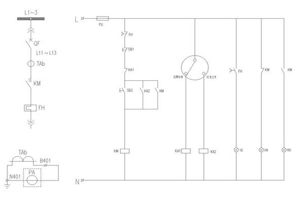
System Sensor B401 Connection Diagram

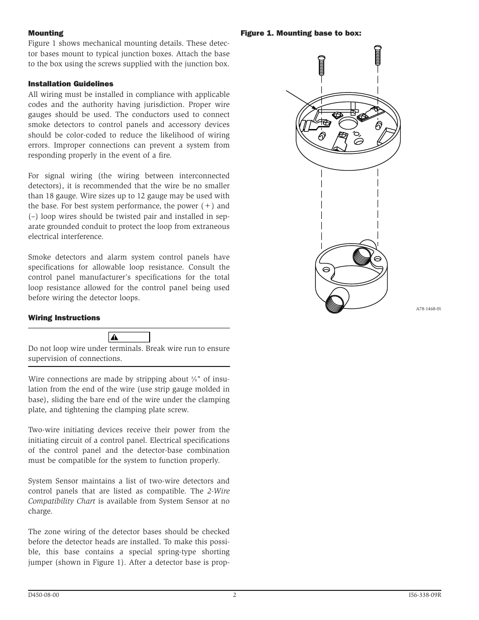
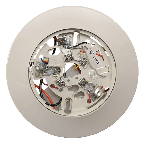
System Sensor Model B401 Detector Mounting Base
System Sensor B401 User Manual Page 2 4 Original Mode
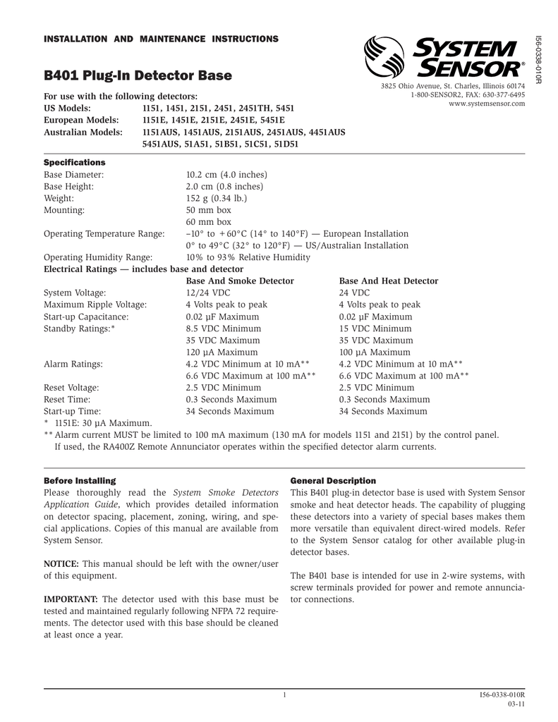
B401 Plug In Detector Base Manualzz

B401 Products System Sensor System Sensor

B114lpbt Plug In Detector Base Manualzz

Conventional Detectors Pertronic Industries

Height 50 mminstalled in b401 base diameter 102 mminstalled in b401 base weight 2 8 oz.
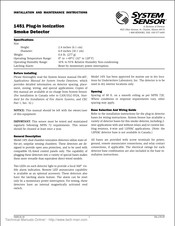
System sensor b401 connection diagram. The capability of plugging these detectors into a variety of special bases makes them more versatile than equivalent direct wired models. Maintenance red blink every 5 seconds amber blink the sensor is outside of its sensitivity limits and shall be cleaned or replaced. Specifications images and particulars in relation to products are subject to change without prior notice and flamestop australia will not be held liable in any way for any errors or omissions. Please thoroughly read the system sensor manual i56 407 guide for proper use of system smoke detectors which provides detailed information on detector spacing placement zoning wiring and special applications.
See section 9 for details. B401 products system sensor system sensor. Cop ies of this manual are available at no charge from system sensor. B401 plug in detector base for system sensor conventional detectors.
This b401 plug in detector base is used with system sensor smoke and heat detector heads. This tool may also be used to access operating data from the detector see the operating manual for the tool for further details. Alarm solid red solid red the unit is in alarm. 80 g operatingtemperaturerange 0 c to38 c 32 f to100 f.
The capability of plugging these detectors into a variety of special bases makes them more versatile than equivalent direct wired models. Are set using a dedicated tool available from system sensor. This b401 plug in detector base is used with system sensor smoke and heat detector heads. Warning several different sources of power can be connected to the fire alarm control panel.
System sensor is a global manufacturer of fire and life safety devices in smoke detection carbon monoxide detection and notification technology. Installation precautions installation precautions adherence to the following will aid in problem free installation with long term reliability. Ensure the sensor is secured in place and the sensor wires are properly connected. Peter christofferson created date.
Page 1 ifs 2600 fire indicator panel technical programming installation manual 3 01 8 05 08 rev. Refer to the system sensor catalog for other available plug in detector bases.

Conventional Spot Type Smoke Detector Bases System Sensor
Http Www Systemsensor Com Cn Uploads 201505 55601ffab48bc Pdf

B401 Helper Group هيلبر جروب
A Smoke Detector Electrical Wiring In Series Diagram Smoke Alarm Interface How To Wire Smoke Detectors In Series Diagram Wiring Excellent Tyco Smoke Detector Wiring Diagram How To Wire Smoke Detectors How
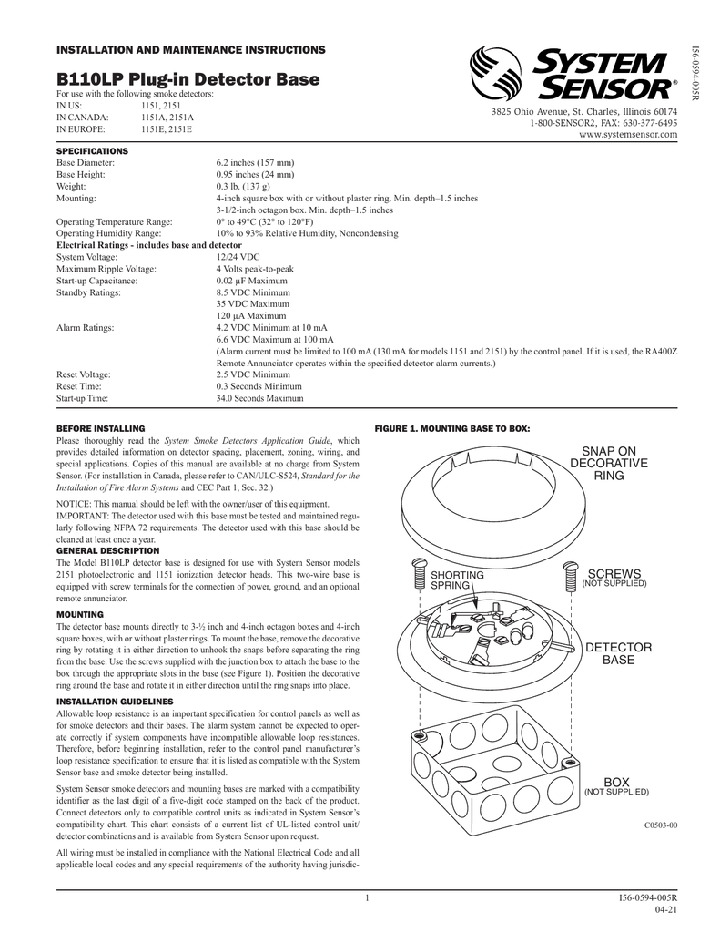
B110lp Plug In Detector Base Manualzz

Notifier B401 Detector Base
Https Www Systemsensor Com Cn Uploads 201508 55be5d6c79fd2 Pdf
Http Ravelfire Com Wp Content Uploads 2015 06 Re316 Installation Manual Pdf

System Sensor B401 Plug In Detector Base Fire Supplies

B401 System Sensor
B114lpbt System Sensor B114lpbt Detector Base Ssd Series 100 24v Dependable Work Lights Your Online Store For Worklights Flashlights And More

Installation And Maintenance Instructions For Model 2351e Low Profile Photoelectronic Smoke Detector Manualzz
System Sensor 1451 Installation And Maintenance Instructions Manual Pdf Download Manualslib

System Sensor B112lpa Plug In Detector Base For Sale Online Ebay
Https Tycosafetyproducts Anz Com Public Manuals Lt0181 Pdf

Cat 2006 5451 Plug In Heat Detector Secutron

System Sensor Plastic Smoke Detector Sensor Pack Of 2 Amazon In Home Improvement

Low Profile Photo Smoke Detector Archer
Https Encrypted Tbn0 Gstatic Com Images Q Tbn 3aand9gct1nct Nfc0kx2qqtjvfqqjd2q3mwbdldb0ipzlucj3htvd2r 8 Usqp Cau

36f Smoke Detector 2151 Wiring Diagram Wiring Library
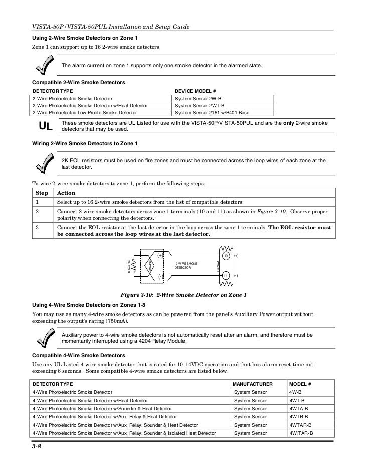
Honeywell Vista 50p Install Guide
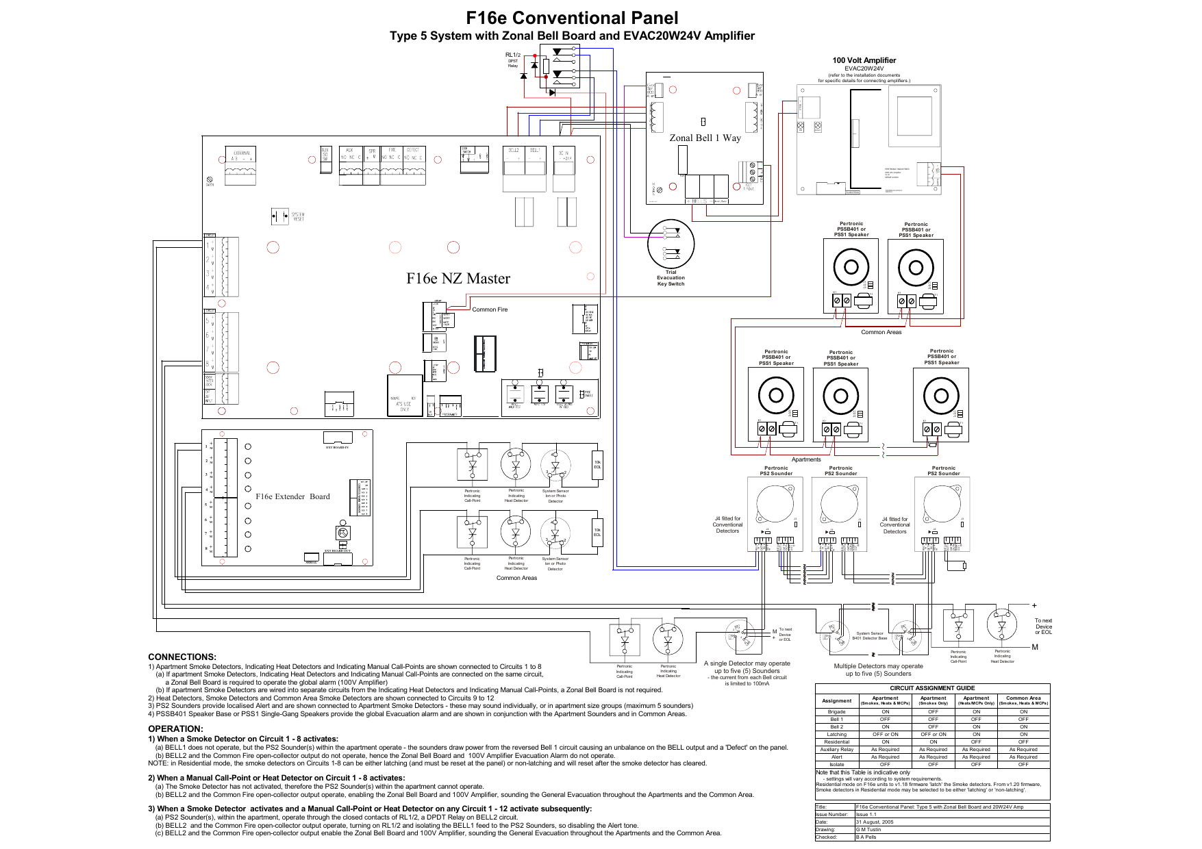
F16e Conventional Panel Type 5 With Zonal Bell Board And Manualzz

Sharp Mx B401 Pdf Fax Electrical Connector
Https Www Firelite Com Catalogdocuments Df 50547 Pdf

Manual Tap Tone 500 Electrostatic Discharge Personal Computers

System Sensor 2151 2151t Installation Manual Alarm Grid
Fgvvizsgwx V9m

Molecular Structures Of Mendomer Series A 400 B 401 And C 602 Download Scientific Diagram
Https Www Tycosafetyproducts Anz Com Public Brochures Jci Nz Catalogue Iss2 2 A4 Pdf

Caterpillar C15 Fuel Injector Wiring Diagram Diagram Base Website Wiring Diagram Venndiagramproblems Inadda It

Inspection Procedure 2 Communication With The Etacs Ecu Is Not Possible
Oki B431l6 Maintenance Manual Pdf Download Manualslib
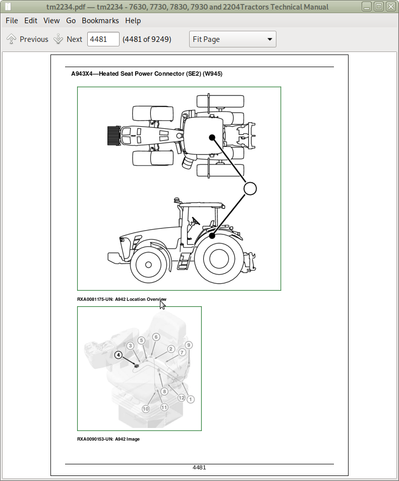
John Deere Tractors 2204 7630 7730 7830 7930 Worldwide Edition Diagnosis And Tests Service Technical Manual Tm2234 A Repair Manual Store
Dd6l Lqk0jjo3m
Http Www Mindraynorthamerica Com Cmsadmin Uploads 0522revk Gas Mod Svc Addendum Pdf
How To Adjust Automatic Water Pump Pressure Controller J T

Collins 180l 2 3 Automatic Antenna Tuners

Position Signal An Overview Sciencedirect Topics
Http Cds Cern Ch Record 1516892 Files Liste 20des 20publications 20du 20cern Pdf
Https Digitalcommons Du Edu Cgi Viewcontent Cgi Article 2690 Context Etd
Http Www Haulotte Com Au Sites Haulotte Au Files Fichiers Pages Htl4010 Training Manual Pdf

Applied Organometallic Chemistry Vol 32 No 3
Peugeot 405 Manual Part 66

