Sync Check Relay Settings

Generator Synchronizing Check Protective Function Ansi 25 Code Eep

Sync Check Relay Synchronization Of A Machine With A Power System Youtube
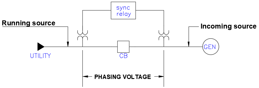
Understand Synchro Check Relay For Source Paralleling Voltage Disturbance
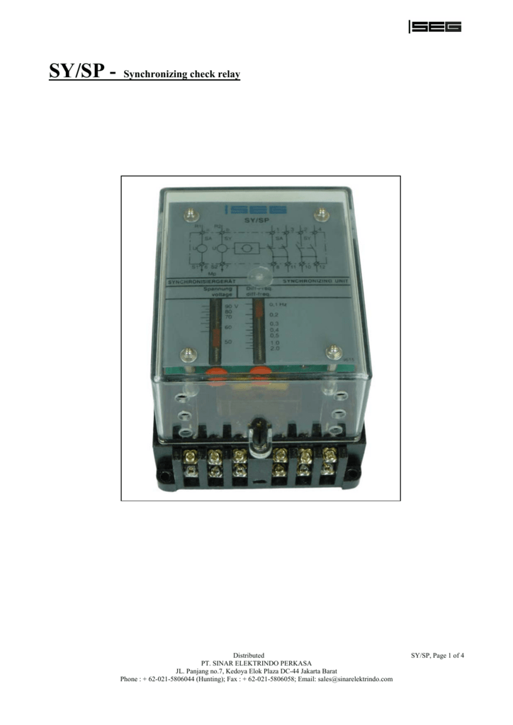
Sy Sp Synchronizing Check Relay
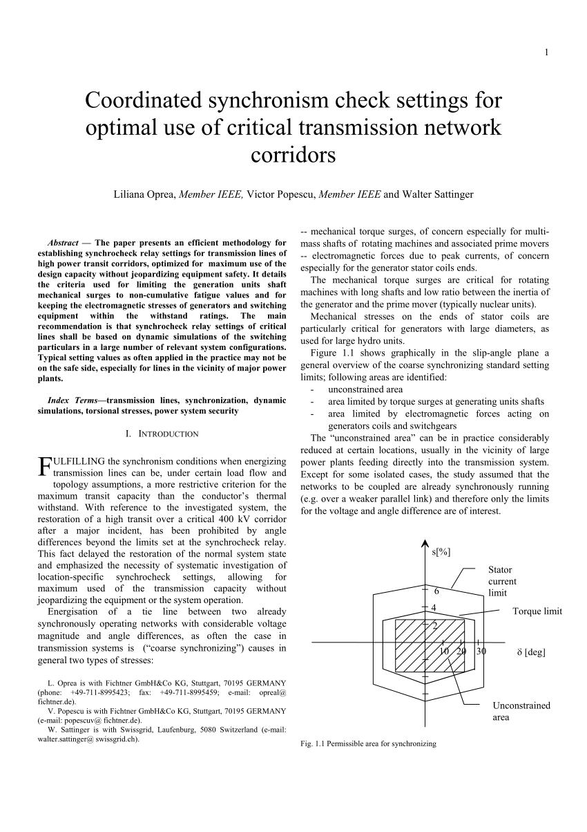
Pdf Coordinated Synchronism Check Settings For Optimal Use Of Critical Transmission Network Corridors
Check Synchronous Relay Working Principle Ske Relay Ansi Code 25 Electrical4u
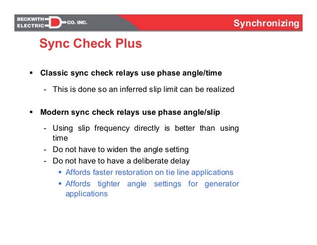
The proposed default angles are 5 degrees advance and 5 degrees late.
Sync check relay settings. In the design of electrical power systems the ansi standard device numbers ansi ieee standard c37 2 standard for electrical power system device function numbers acronyms and contact designations identifies the features of a protective device such as a relay or circuit breaker these types of devices protect electrical systems and components from damage when an unwanted event occurs such. Voltage settings for sync check relays have a voltage hi and voltage lo settings. 1 to on and condition sw. Now to make the setting of system split go to menu system sync and set your values here.
Sync relay contacts closed by voltage monitor logic ov exceeded sync check reclosing not enabled setting mode sw. Now again to configure o p contact go to hmi of the relay and press down arrow until you. The synchro check relay can be used to assist in the semi automatic parallelling of two ac power systems. Go to check synch menu and make system split enable and make the angle 90 degree e g.
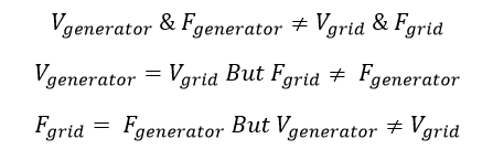
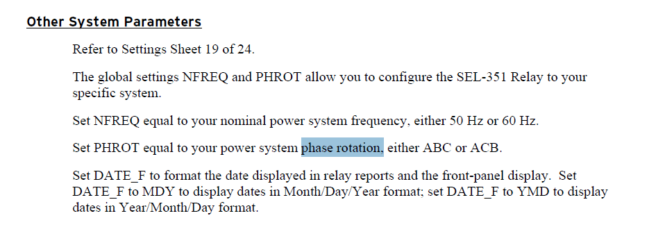
This page contains technical data sheet documents library and links to offering related to this product. For successful synchronization voltage frequency phase rotation and phase angle of the two sources must meet the thresholds set per the user programmable settings in the relay. Figure 1 provides suggested settings for generator sync check relays. If you require any other information please contact us using form located at the bottom of the page.
Then sync check verifies that this angle is less than the front panel phase angle selector setting. Figure 1 synchronizing check relay settings. Synd sync out g1 g2 21 tx l1 l2 l3 l1 l2 l3. Ffi sync check logic enabled no.
1 to on permits ov h bov fixed minimum voltage limit iz zl closing enabled zone live line live bus condition only figure 2 voltage monitor acceptance zones w. The volt free relay contacts change state when the voltage level phase relationship and frequency are within the selected synchronising limits. Sync check relay supervision automatic synchronizer matches v and f and closes. Sync check parameters typical settings regions modify for particular requirements rotating machines bus to bus parameter typical value voltage difference 10 15 v phase slip angle 0 30 slip.
Be1 25 sync check function measures the phase angle between single phase voltages of line and bus. Synd connection diagram function diagram 55 mm 75 mm 100 mm a1 t 4 8 6 sync delay v ϕ vdb u bus 75 u gen 75 t o o f a s t o o s l o w 2 10 8 16 12 4 20 0 4 0 8 0 6 0 2 1 0 4 2 10 synchro check relay b1 b2 12 11 24 t a2 on off ts 2x v dead bus generator type. If the measured angle has met this criteria for the time period defined by the front panel time delay setting the sync output contact closes.
Auto Synch Considerations Methods
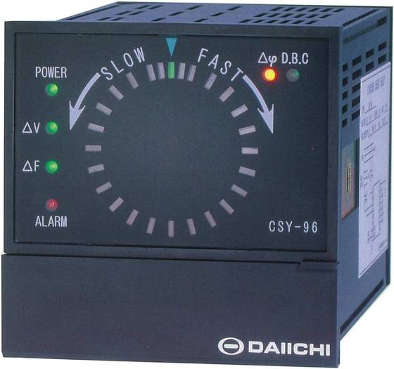
Synchronism Check Relay Csy 96 Id 1569136 Product Details View Synchronism Check Relay Csy 96 From Daiichi Electronics Co Ltd Ec21
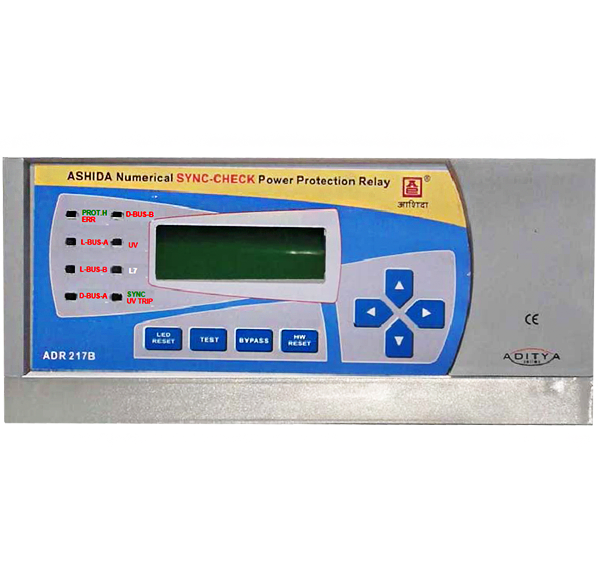
Sync Check Relay Manufacturers In India Ashida Electronics
Https Www Myprotectionguide Com Uploads 7 3 0 1 73017921 Procedure For P143 Pdf
Https Ieeexplore Ieee Org Iel7 8253408 8315543 08315884 Pdf
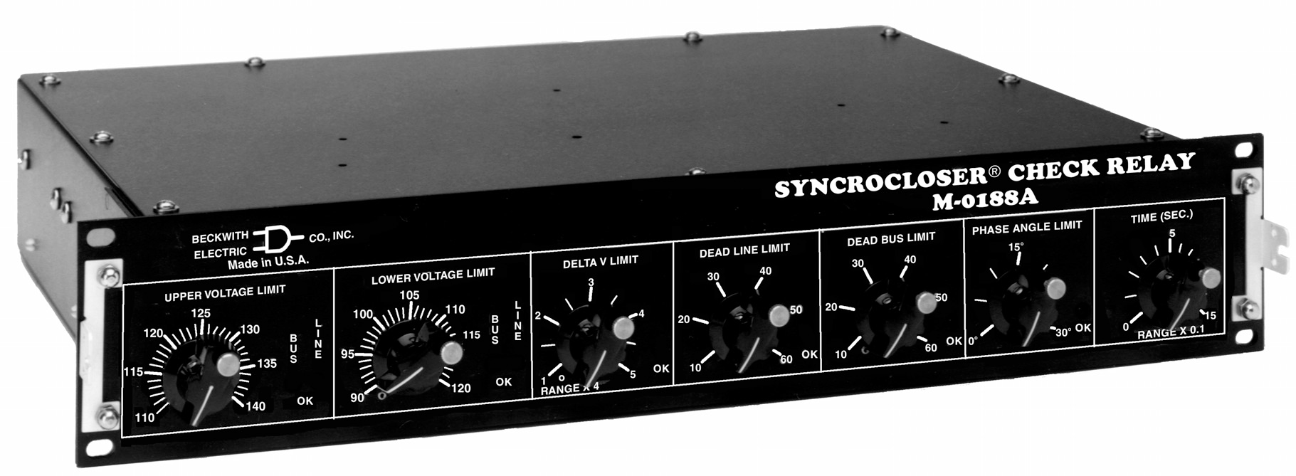
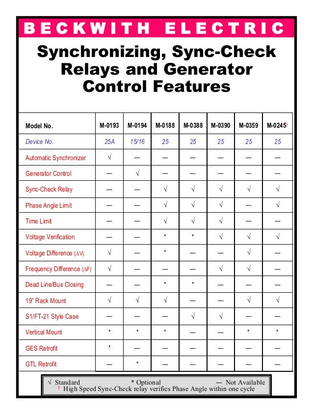
Solutions Synchronizing Systems Beckwith Electric

Synchro Check Relay At Rs 899 Unit Relays Id 9580289012
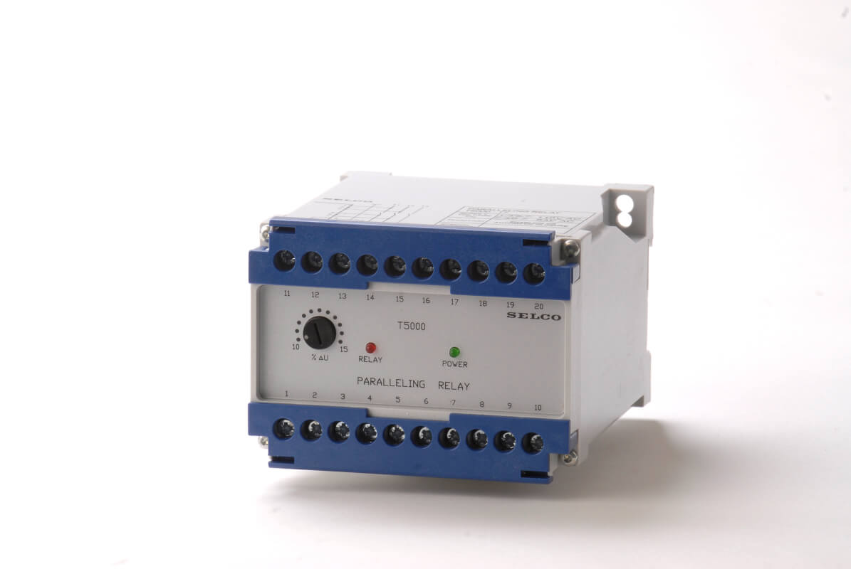
Paralleling Relay T5000 Selco
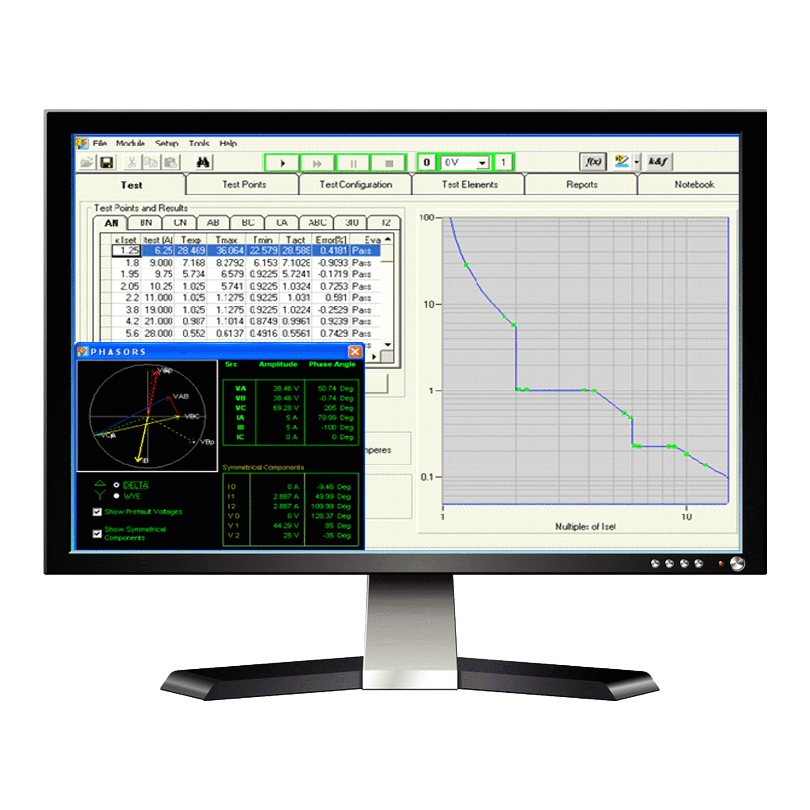
Protective Relay Testing Software From Doble F6test
Https Selinc Com Api Download 128554
Https Store Gegridsolutions Com Faq Documents Gxs Ger 2624 Pdf
Http Www Cce Umn Edu Documents Cpe Conferences Mipsycon Powerpoints 2014 Relayiigetinstepwithsynchronizationareviewofsynchronization Pdf

Synchronization Alternating Current Wikipedia

Synchronizer Omicron
Scr 2 0 Cre Technology
Https Www Beckwithelectric Com Wp Content Uploads Docs Events 2019 Wsu Hands On Relay Beckwith 3425a Handout Pdf
Http Www Mercado Ideal Com Catalogosc Crompton Instruments 20 Tyco 20electronics 20protector 20trip 20relays Pdf
Https Support Industry Siemens Com Cs Attachments 109747294 7sr157 Complete Technical Manual Pdf
Automatic Synch Of Gen

Generator Protection Alstom Micom P343 Testing Procedure
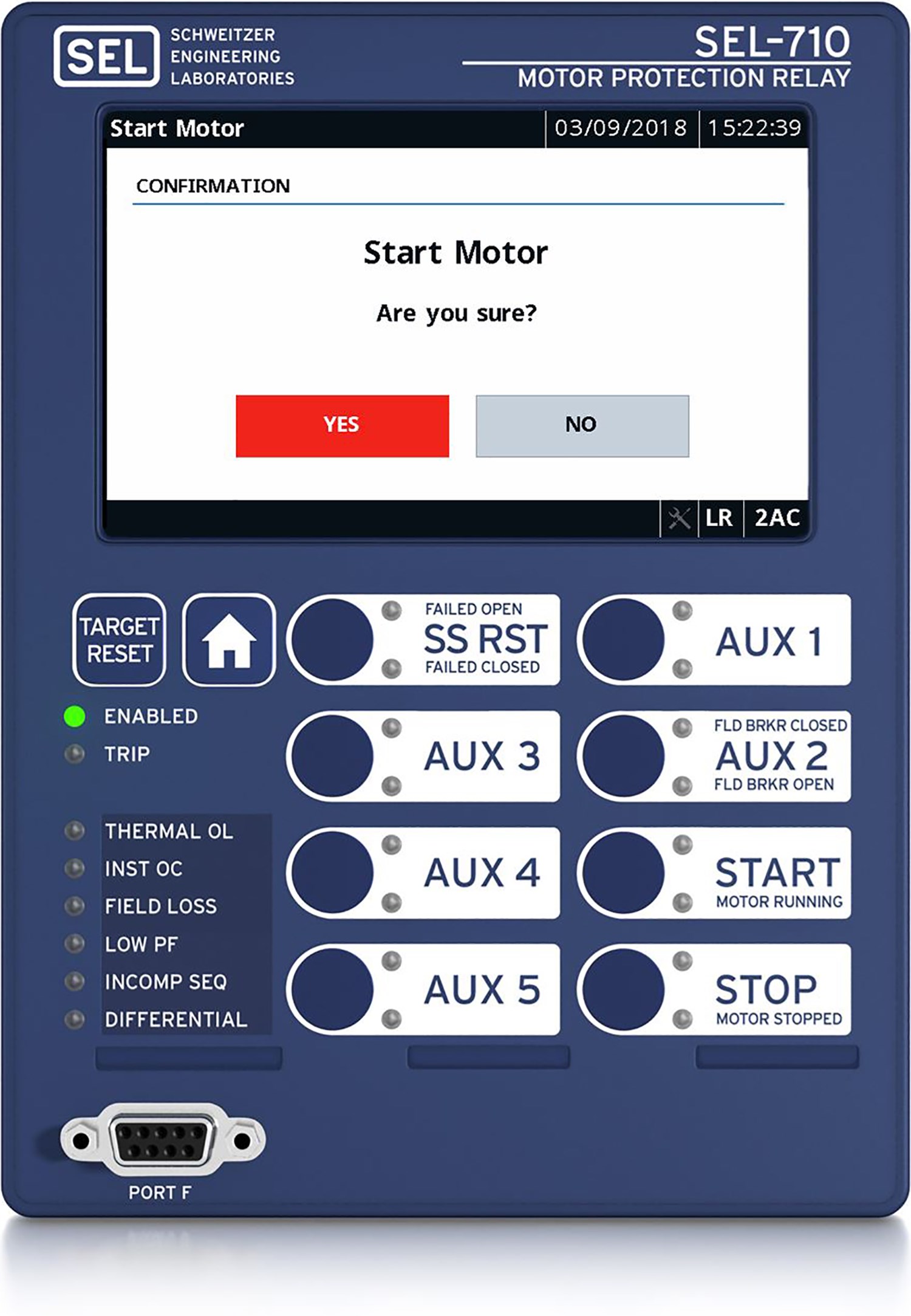
Sel 710 5 Motor Protection Relay Schweitzer Engineering Laboratories
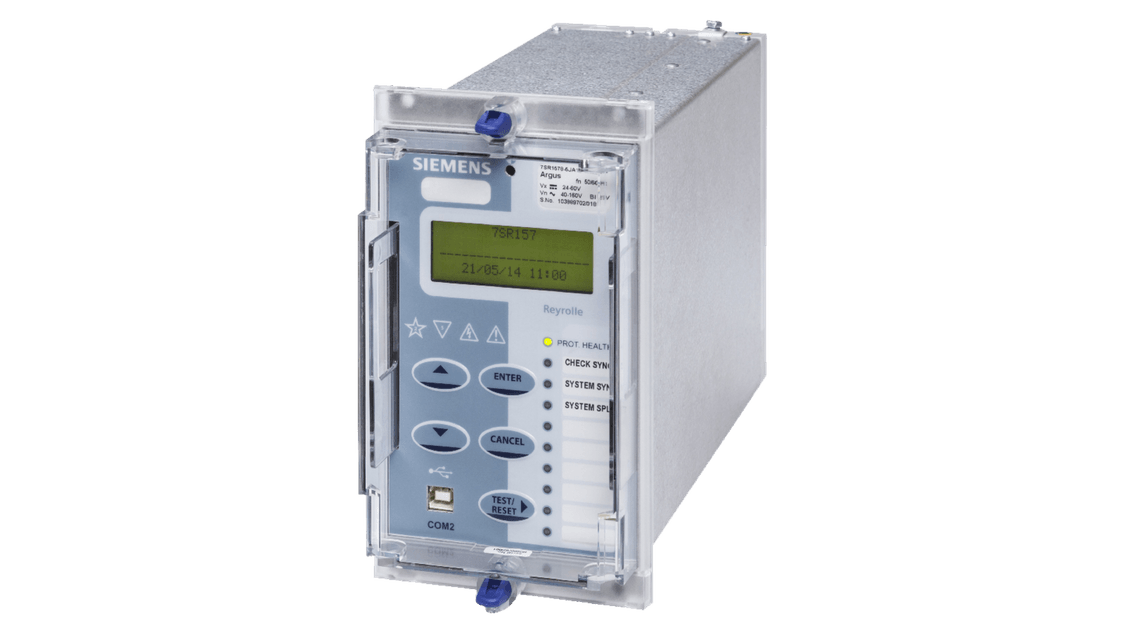
Check Synchronising Reyrolle 7sr157 Synchronizing Global
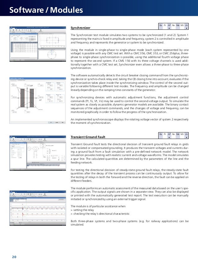
Omicron Testing Solutions For Protection Measurement Systems Omic
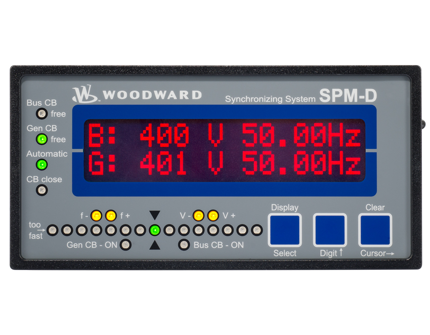
Synchronizers Load Share Controllers Woodward
Https Www Eiseverywhere Com File Uploads 15b6ba8a2779ff744f3e09e5be9b5967 Substationcommissioning Pdf
Https Library E Abb Com Public 74edad084eae4fb8a85d2a3ed1e1afb6 Abb 1798 Wpo Ekip Technical Paper Pdf

Energization An Overview Sciencedirect Topics
Http Download Schneider Electric Com Files P Reference P14x En M Kj8 B2 Lm P Endoctype User 20guide P File Id 4516515991 P File Name P14x En M Kj8 B2 Lm Pdf
Http Www Automation Berlin Com Downloads Siemens Energy Ptd 7vk512x Catalog Sip2004 En Pdf

Salesforce Outlook Integration A Step By Step Guide
Http Ieeexplore Ieee Org Iel7 8358849 8358850 08358851 Pdf
Protection Relay Testing Rb Marine Power Engineering Protection Relay
Https Store Gegridsolutions Com Manuals Documents T60 1601 0090 F1 Pdf

Seven Design Diagrams That Every Hv Substation Engineer Must Understand Eep

3cx Surveyor User Guide Voiptools
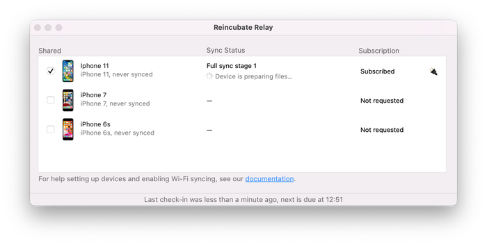
Ricloud Api Relay Icloud Ios Data Access Made Easy

Siris Alto And Nas Device Settings Datto Knowledge Base

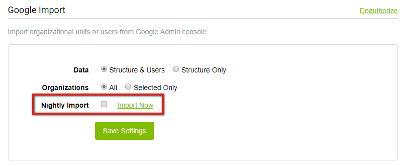
3cx Active Directory Sync Voiptools
Https Selinc Com Api Download 126162
Use Sequence Components To Make Sure Your Relay Isn T Disabled By Incorrect Phase Rotation Valence Electrical Training Services
Lightspeed Systems Inc Relay Settings User Management Lightspeed Systems Community Site
Https Library E Abb Com Public 46718ab30c3eaf6185256eae0065dbde 41 681 1r Pdf

