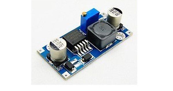
Step Down Buck Converter Circuit

It is a class of switched mode power supply smps typically containing at least.
Step down buck converter circuit. The ac input to the rectifier circuit could be ac at high voltage directly from the ac mains supply or alternatively at a lower voltage via a step down transformer. It is a class of switched mode power supply smps typically containing at least two semiconductors a diode and a transistor although modern buck converters frequently replace the diode with a second transistor used for. The buck converter designed in this project will step down 12v dc to 5v dc with a tolerance limit of 0 5 v. Luckily such a device already exists and it s called a buck converter or step down voltage regulators.
These values will indicate the efficiency of the buck converter designed in the project. It s a type of dc dc converter so it accomplishes the task using a few transistor switches and an inductor. A buck converter step down converter is a dc to dc power converter which steps down voltage while stepping up current from its input supply to its output load. It is a type of switched mode power supply smps comprising of two semiconductors components and an energy storage element.
Vin pin is connected to the 5v power supply gnd pins are connected to the gnd and vout pin is connected to the analog output pin. The input voltage source is connected to a controllable solid. Introduction to buck converters. In the diagram of the current waveforms for the buck converter switching regulator it can be seen that the inductor current is the sum of the diode and input switch current.
However the dc applied to the buck converter is obtained it is then converted to a high frequency ac using a switching or chopper transistor driven by a usually pulse. A typical buck converter is shown below. A buck converter step down converter is a dc to dc power converter which steps down voltage while stepping up current from its input supply to its output load. Capacitor based filters are usually added to reduce voltage ripple.
In this project we are going to make a buck converter circuit using arduino and n channel mosfet with a maximum current capacity of 6 amps. Dc to dc buck converter diy how to step down dc voltage easily. Dc dc converters are also known as choppers. Here we will have a look at the step down chopper or buck converter which reduces the input dc voltage to a specified dc output voltage.
We can control the output voltage value by rotating the potentiometer. A buck converter step down converter is a dc to dc power converter used to step down voltage while stepping up current. Lm317 dc to dc converter step down circuit 1 pin m m connectors 2 4mm screw driver usb cable 1. Connect the components based on the figure shown in the wiring diagram using a m m pin connector.
A typical buck converter circuit is shown in the above image.


