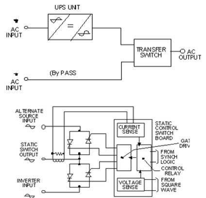
Static Switch Circuit Diagram
Static Transfer Switch

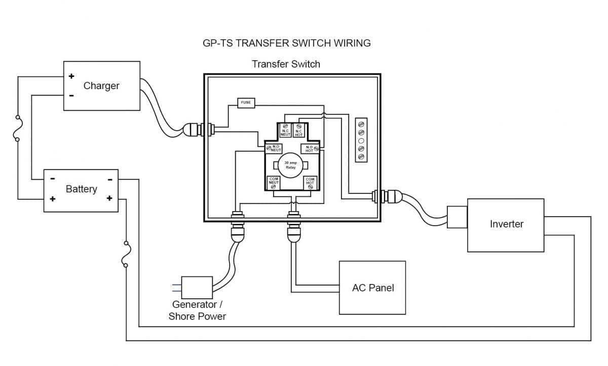
Generator Transfer Switch Wiring Diagram Generator Transfer Switch Transfer Switch Solar Energy Information

Image Result For Generator Transfer Switch Wiring Generator Transfer Switch Transfer Switch Generation

Image Result For Generator Transfer Switch Wiring Transfer Switch Generator Transfer Switch Electrical Circuit Diagram
Pinnacle Static Transfer Switch

Manual Changeover Switch Wiring Diagram For Portable Generator Transfer Switch Generator Transfer Switch Outlet Wiring

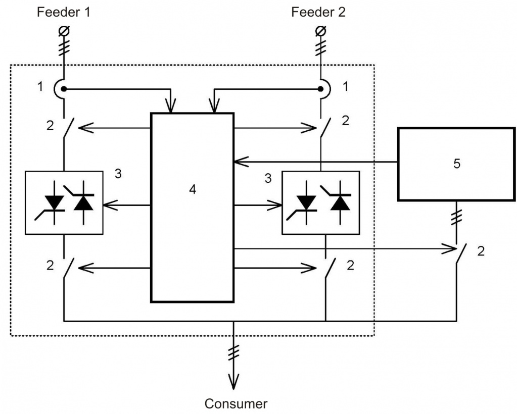
The block diagram of a static switch is shown below.
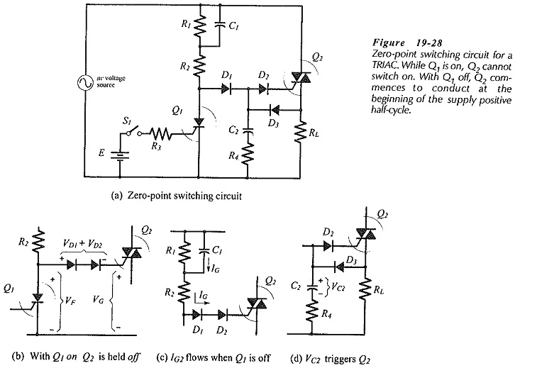
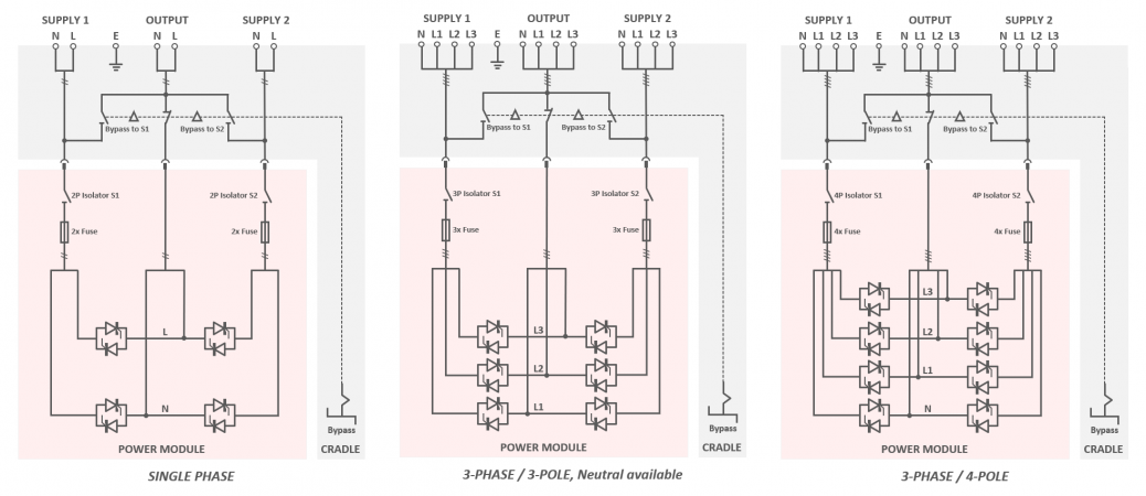
Static switch circuit diagram. Silicon controlled rectifiers of which the internal structure is made up of. During the positive half cycle of the sinusoidal waveform the device is forward biased but with switch s 1 open zero gate current is applied to the thyristor and it remains. 3 way switched outlet wiring. In some ups installations the transfer is delayed for a finite time to allow a load protection fuse or circuit breaker to act and clear the fault so avoiding subjecting the load to raw mains or even.
The above thyristor firing circuit is similar in design to the dc scr circuit except for the omission of an additional off switch and the inclusion of diode d 1 which prevents reverse bias being applied to the gate. Current flow will be through load r l s 1 r 1 and gate to mt1 junction of the thyristor. Control system and metering system. The circuit operation occurs when switch s 1 is closed since the triac q 1 will initially be in the block ing condition.
A ups bypass switch is a non essential addition to an uninterruptible power supply system that while not integral to ups operation is definitely useful in the event of maintenance or repair. Capable of providing all information concerning equipment operation status. When this current reaches. When a deviation from the pre set limits on the preferred source is detected a transfer signal is generated.
A breaker or a bus assembly. The source is at the sw1 where the hot is connected to. Three wire cable runs between the switches and the outlet. Sts 4p 100 400 600 a static switch is fitted with a block diagram with led indicators and a 4 line 20char display.
Static switches play a key role in assuring this resilient performance. An online system can also use the static switch to transfer the load to bypass if an overload condition drawing excessive current develops. Static transfer switch b. The core items you need in order to be protected in the event of power failure are a ups and a battery to supply the power under standard operation this should be all that is required.
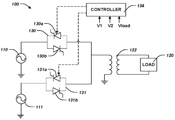
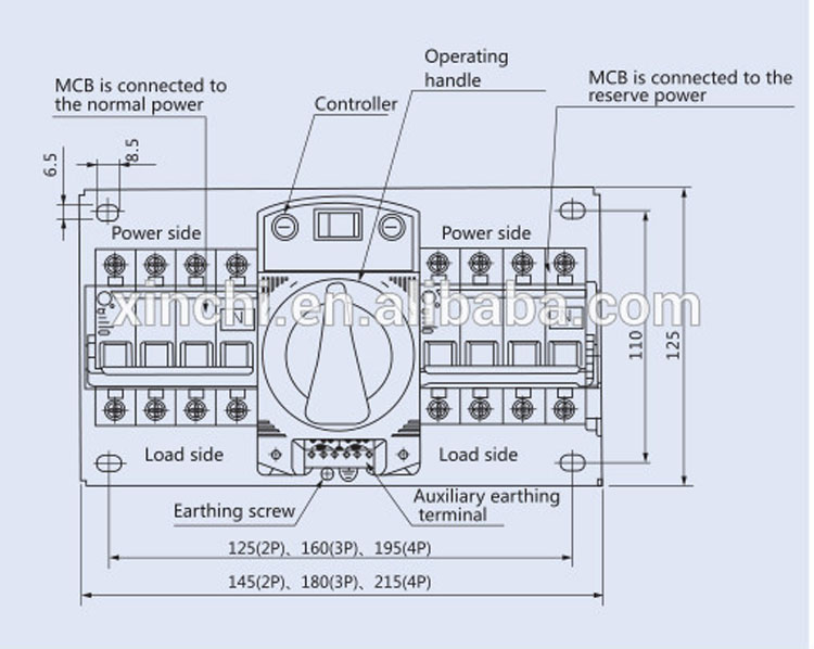
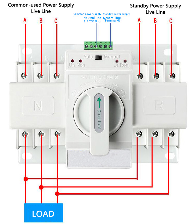
Parts of a static transfer switch. In this diagram two 3 way switches control a wall receptacle outlet that may be used to control a lamp from two entrances to a room. A transfer switch is an electrical switch that switches a load between two sources. Today s upss that use modular technology are flexible and easily scalable while protecting their critical load from many different threat types.
Together with the power source priority selection button enables operators to make full use of the apparatus. Some transfer switches are manual in that an operator effects the transfer by throwing a switch while others are automatic and trigger when they sense one of the sources has lost or gained power. Typical static switch circuit. A static power transfer switch consists of three basic parts.

How To Wire Ups Inverter With Automatic Changeover Switch Transfer Switch Electrical Diagram Switch

Automatic Transferred Switch Ats Circuit Diagram Electrical Engineering Blog Transfer Switch Circuit Diagram Electrical Wiring Diagram

Wiring Riddle No 3 Auto Transfer Switching Diagram Teknik Listrik Teknik Listrik

Gentran Transfer Switch Wiring Diagrams Transfer Switch Generator Transfer Switch Switch

Manual Changeover Switch Wiring Diagram For Portable Generator Or How To Connect A Generator To House W Transfer Switch Generator Transfer Switch Outlet Wiring

Pin By Denis Pu On Groupe Electrogene In 2020 Portable Generator Transfer Switch Home Electrical Wiring

Typical Automatic Transfer Switch Block Diagram Find More About Automatic Transfer Switch On Http Yout Generator Transfer Switch Transfer Switch Generation

Generator Changeover Switch Wiring Diagram As Well As Solar Transfer Switch Generator Transfer Switch Electrical Projects

Circuit Diagram Of Automatic Tranfer Switch Transfer Switch Pic Microcontroller Microcontrollers
Thyristor Circuit And Thyristor Switching Circuits

Image Result For 3 Phase Changeover Switch Wiring Diagram Transfer Switch Circuit Diagram Electrical Wiring Diagram

Wiring Riddle No 3 Auto Transfer Switching Control Diagram Automatic Transfer Switch At Transfer Switch Electrical Circuit Diagram Generator Transfer Switch

Generator Transfer Switch Wiring Google Search Generator Transfer Switch Transfer Switch Electrical Projects

Automatic Transfer Switch Switch Between Solar Generator And Main Grid Power Ats Diy Tech Repairs

Automatic Transfer Switch Single Line Diagram Representation Single Line Diagram Line Diagram Transfer Switch

Automatic Transfer Switch Switch Between Solar Generator And Main Grid Power Ats Diy Tech Repairs Transfer Switch Electrical Circuit Diagram Switch
Https Www Powersystemsinternational Com Wp Content Uploads 2017 02 Static Transfer Switches 2017 Pdf
Automatic Transfer Switches Mobile Solar Power Made Easy
Https Encrypted Tbn0 Gstatic Com Images Q Tbn 3aand9gcr17 Ble5wxj3xskphuxcf3ouol5y3hs1yeu Cksjjsuaz0y4tf Usqp Cau

Electrical Wiring Be28 Automatic Transfer Switch Controller Connections Diagra Diagrams Electrical Circuit Diagram Transfer Switch Electrical Wiring Diagram
Low Voltage Installation Static Transfer Switch Sts

Generac Manual Transfer Switch Wiring Diagram Transfer Switch Generator Transfer Switch Switch

Gentran Vinatage Models Manual Transfer Switch Wiring Diagram 1 Gif 450 439 Electricidad Electrica Electronica

Diagrama De Cableado Cableado De Un Generador Portatil A Casa Manual Del Diagrama De Cableado Del Transfer Switch Portable Generator Generator Transfer Switch

How To Connect A Portable Generator To The Home Supply 4 Methods In 2020 Home Electrical Wiring Electrical Projects Electrical Wiring

Rvelectricity Generator Automatic Transfer Switches 101 Rv Travel
Static Transfer Switch Sts Ists Model B2 Static Power

How To Connect A Portable Generator To The Home Supply 4 Methods Transfer Switch Portable Generator Emergency Generator
Sq3n Watsn Automatic Static Transfer Switch China Suntree Electric

3 Phase Manual Changeover Switch Wiring Diagram Changeover By Tech Bon Generator Transfer Switch Electrical Circuit Diagram Switch

Gc 0215 Generac Battery Charger Wiring Diagram Download Diagram
Automatic Transfer Switch 3 4 Pole 6 To 63 Amps Ato Com
Understanding Transfer Switch Transition Types

Touch On And Off Switch Circuit Diagram And Working Circuit Diagram Circuit Electronic Schematics

3 Different Method Of Staircase Wiring With Diagram And Complete Staircase Circuit Guide Home Electrical Wiring Light Switch Wiring Electrical Wiring
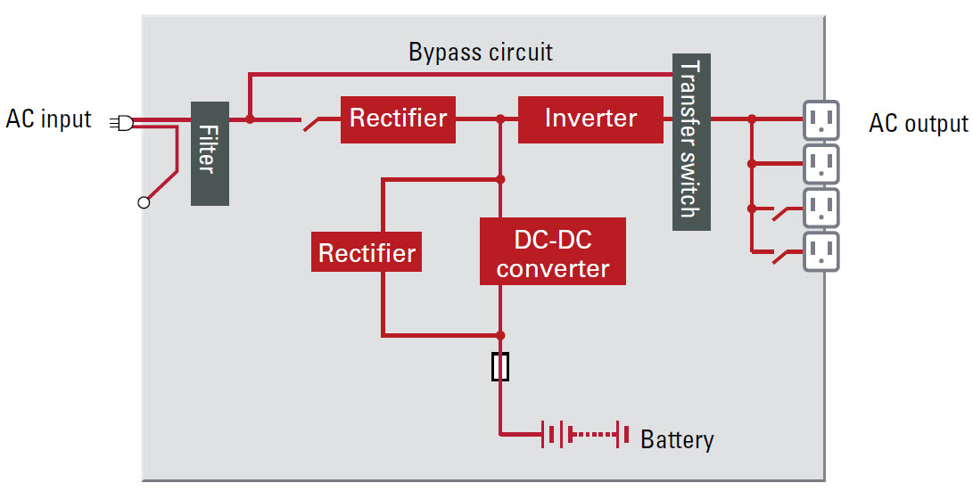
Ups Main Components Republic Power Systems

Diesel Generator Control Panel Wiring Diagram Engine Connections Electrical Circuit Diagram Basic Electrical Wiring Electrical Wiring Diagram

How To Make Solid State Relay Diy Electronic Schematics Electronic Circuit Projects Relay

Ups Systems What Does On Line Double Conversion Mean
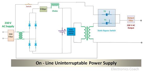
Difference Between Online Ups And Offline Ups With Comparison Chart Electronics Coach

Spartan Power Sp Ts4500 12 12v Dual Power Transfer Switch

Transfer Switch Options For Portable Generator Transfer Switch Generator House Generator Transfer Switch